NES Boy


")


The second NES system I put in a GameBoy case. This one has a few improvements over that last design, but a few things left out as well.
Features:
- LED backlit screen for more battery life.
- Runs on 4 AA rechargeable batteries. The system will run for around 7 hours.
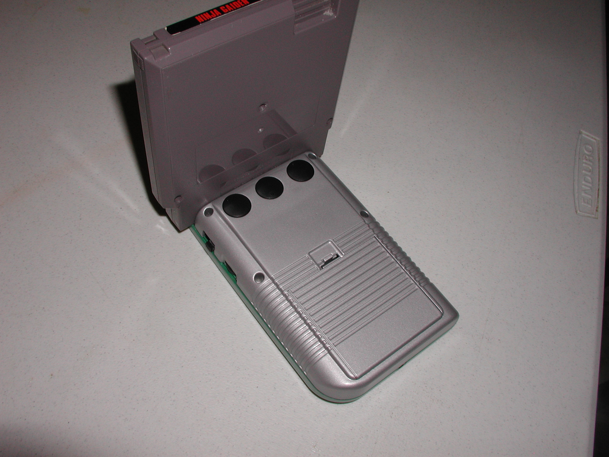
- Adjustable knobs on the back set the color, brightness, and contrast for a perfect image.
- The original volume wheel adjusts the volume.
- Headphone jack works. When a headphone is plugged in, the speaker is disconnected.
I decided to make this because I had an extra NES clone lying around. Unfortunately this one did not have built in games, so a cartridge must be used. I also did not bother with a TV out or a player 2 port because I rarely used them on the NES p0cket.
I removed the LCD’s CCFL backlight and replaced it with two white LED’s. With that done I did not need to have any higher voltage than 5V to run the system. So I was able to use 4 rechargeable AA’s (4.8V) for power. I was a bit worried but the backlight worked great! You can see where the LED’s in the corners are a bit brighter than the rest of the screen, but it’s hardly noticeable and well worth the power savings.
Build Pics
Parts used:
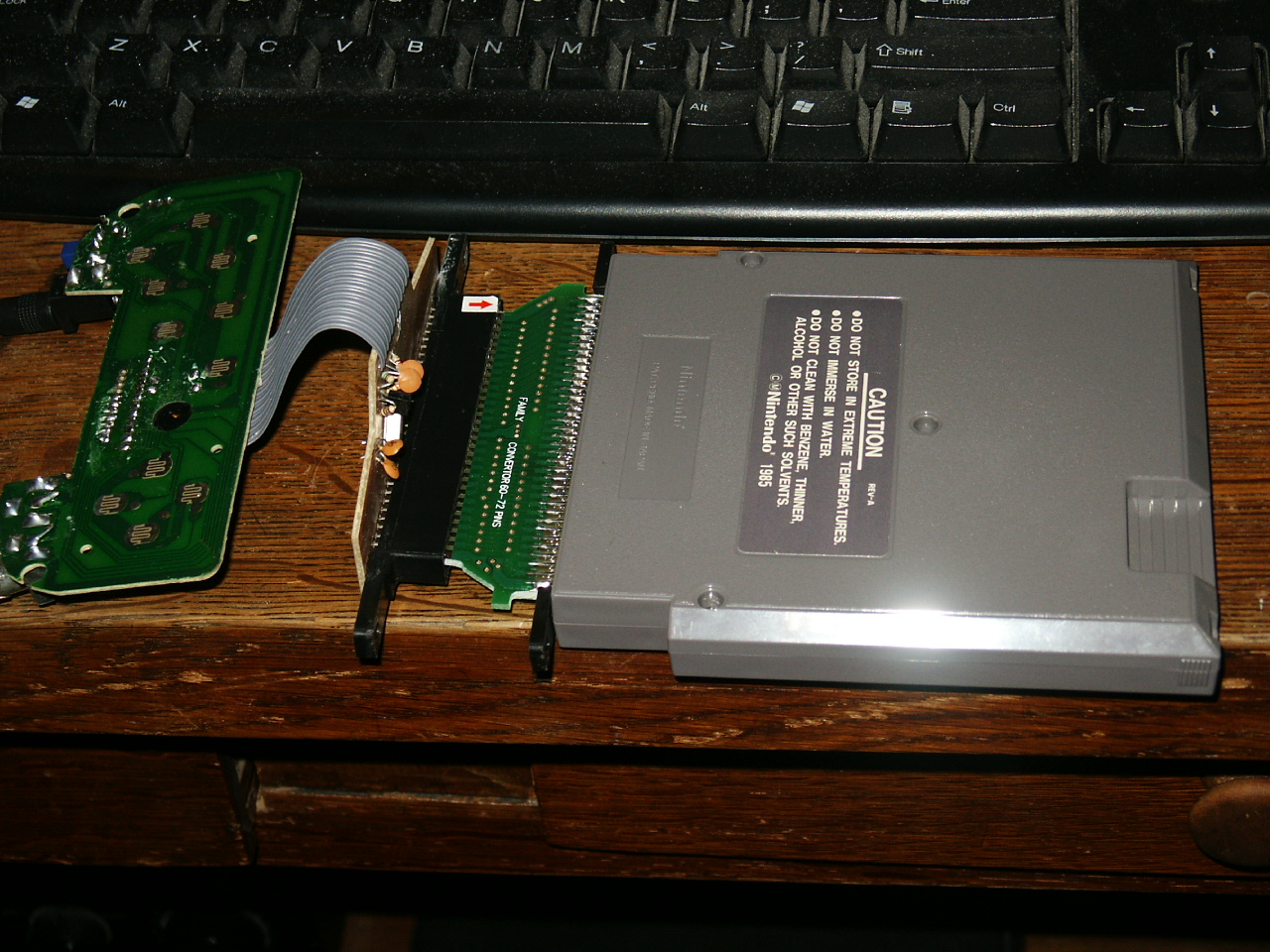
- Generic NES clone
- LCD taken from a Hip Gear game controller
- GameBoy case
")
")
")
")
")
")
")
")
")
The NES clone was a Famicom (Japanese NES) clone, which has a smaller connector with 60 pins. American cartridges have 72 pins. Fortunately they sell adapters for this. I traced all the pins from the cartridge to the board and then cut off the connector and wired it up. For the audio amp I traced the pins on the Hip Gear board and remade it on some PCB.
For the controls I reused the original GameBoy board. I also used the controller IC that came with the system, and cut it down to size. Then wired it all up. Everything was then either screwed, hotglued, or superglued in place.
The LCD didn’t quite fit the paneling of the original GameBoy screen cover, so I used grip tape made for stairs to cover the edges of the screen.

Very nice thats an awesome screen and also its quite clean nice job
Yeah, for the price at the time quite a nice screen, and you got a controller with it! Nowadays there are better options, but it was a good deal back then.